In the realm of CNC machining, among various precision machining processes, face milling stands out as a common mechanical method capable of meeting the demands of intricate product designs.
But did you know? Different face milling operations entail vastly different requirements for cutting tools. Factors such as cutting speed and material removal capability are crucial considerations when selecting tools. Therefore, to ensure smooth project execution, a profound understanding of face milling processes is indispensable!
In this article, we delve into the working principles of face milling, the selection of appropriate face milling tools, and various types of face milling operations. Whether you’re a novice or seasoned engineer, if you seek insights into face milling, this article will be the ultimate guide..
What is Face Milling?
Face milling is a specialized machining technique used for leveling and smoothing the surface of workpieces. This technique involves not only precisely removing excess material from the workpiece using cutting tools but also its distinctive machining angles and methods.
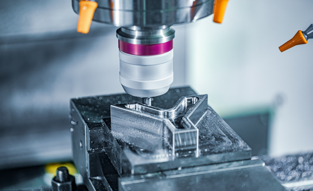
Compared to traditional milling processes, the most prominent feature of face milling lies in the placement of the cutting tool (common face milling tools include shell mills, end mills, and fly cutter). In face milling, the rotation axis of the cutting tool, also known as the tool axis, is ingeniously positioned perpendicular to the workpiece. Such a design enables the cutting tool to engage with the workpiece from a completely new angle, thereby achieving efficient and precise machining of the workpiece surface.
Imagine the teeth of the cutting tool facing downwards, closely adhering to the top of the workpiece. As the workpiece slowly passes through the cutting tool, the tool rotates counterclockwise, and its sharp teeth act like precise blades, gradually removing excess material from the workpiece surface. This process not only tests the skills of the machinist but also demonstrates the finesse and efficiency of the face milling process.
Difference Between Face Milling vs Peripheral Milling
Face milling and peripheral milling are the main types of CNC milling processes, both relying on rotating cutting tools to remove material from the workpiece surface. Below is a detailed comparison of these two machining methods:
Face milling is a machining method focused on the surface of the workpiece, using flat milling cutters for fine machining of the workpiece surface. Peripheral milling, on the other hand, utilizes cutting edges distributed on the cylindrical surface of the milling cutter for milling, mainly used for machining flat surfaces that are not too wide or narrow. For surfaces wider than 120mm, peripheral milling may not be suitable.
Face milling primarily relies on the top of the cutting tool for milling action. Since the tool axis is perpendicular to the workpiece, only the top of the tool can contact the workpiece surface and perform cutting. Peripheral milling involves the side of the workpiece, with the tool cutting on the side of the workpiece to remove material.
Face milling is more suitable for surface machining and removing a small amount of material from the workpiece. Due to the characteristics of its cutting method, face milling can achieve fine machining of the workpiece surface, improving surface finish and accuracy. Peripheral milling, on the other hand, is more suitable for removing a large amount of material from the workpiece, especially in roughing and semi-finishing operations, where its cutting efficiency is higher.
Face milling can be performed on machines with both horizontal and vertical spindles, offering greater flexibility. Peripheral milling, on the other hand, is mainly suitable for machines with horizontal spindles, with its application range relatively limited.
How Does Face Milling Work?
The process of face milling can be subdivided into the following four core steps, each of which is crucial to the final machining quality and efficiency.
1.Workpiece positioning
Before face milling, stabilize and secure the workpiece on the worktable to ensure it does not move or vibrate during the entire machining process.
2.Machine alignment and tool selection
Adjust the milling machine to a position perpendicular to the workpiece to ensure accurate machining of the workpiece surface by the tool’s top. Simultaneously, choose the appropriate face milling cutter based on the material, shape, and machining requirements of the workpiece to ensure sharpness and durability of the tool.
3.Adjust feed rate and spindle speed
The feed rate determines the speed at which the workpiece moves during machining, while the spindle speed affects the rotation speed of the tool. Adjust these two parameters according to the material, thickness, and machining requirements of the workpiece to achieve the best machining results.
4.Machining and monitoring
Once all preparations are complete, start the CNC machine for machining. At this point, the machine will automatically follow the preset program for machining, while the machinist closely monitors the process to ensure everything runs smoothly.
Choosing the Ideal Cutting Tool for Face Milling
In face milling, shell mills, end mills, and fly cutters are the three main tool choices.
Shell Mill
Shell mills are the most commonly used tools in face milling. Equipped with multiple teeth and cutting edges mounted on the periphery, this cutting tool effortlessly creates highly consistent surface finishes. As shown in the figure below.
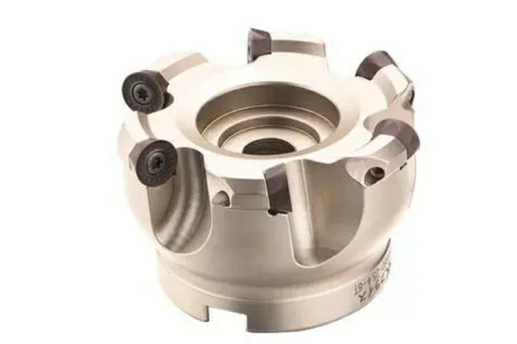
This design not only controls the amount of material removed with each cut but also provides balanced cutting forces. Additionally, shell mills are suitable for processing a variety of materials, making them widely applicable.
However, it is important to note that depending on the hardness of the material, the cutting inserts of shell mills may need to be replaced regularly to maintain their cutting performance.
Fly Cutter
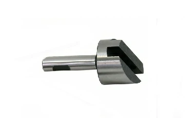
A fly cutter features only one cutting edge and one blade, primarily used for machining large surfaces. There are various types of fly cutters, including single-point fly cutters (where “single-point” refers to the cutting tool having one cutting edge capable of removing material in a single pass) and rotating-bend tools.
They can produce fine surface finishes with low energy consumption. Therefore, for machining tasks where high-quality surface finishes are desired while minimizing energy consumption, fly cutters are an ideal choice.
For more detailed information about flying knives, please read this article: Exploring Fly Cutter: Precision Machining at Its Finest
End Mill
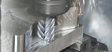
End mills are renowned for their unique cutting edge design, used to create flat surfaces along the axis of a high-speed rotating spindle, particularly suitable for intricate finishing operations on workpieces. However, when handling machining tasks requiring the removal of large amounts of material, end mills may not be the optimal choice.
Furthermore, due to their relatively weaker structure, end mills may be limited in processing certain materials. Therefore, when selecting end mills, a balance needs to be struck based on specific machining requirements and material characteristics.
Tips For Choosing The Right Face Milling Tool
When it comes to selecting the optimal face milling tool, different types of face milling operations require different choices. Here are several key points and in-depth explanations to help you choose the right tool for specific tasks.
When dealing with hard materials, shell mills are the preferred choice. Their design, featuring multiple cutting edges, allows them to efficiently remove large amounts of material.
For machining softer materials, fly cutters are the ideal face milling tools. Their design enables them to produce fine surface finishes with low energy consumption.
If you need to create aesthetically pleasing designs through face milling, end mills will be your best bet. End mills are equipped with multiple teeth on the shank, allowing them to adapt flexibly to various machining requirements, whether it’s smooth curves or intricate patterns.
In addition to tool type, the angle at which the tool enters the workpiece is also an important consideration. Most tools enter the workpiece at either a 45° or 90° angle.
Choosing between 45° and 90°?
A 45° cutting edge is more suitable for high-demand cutting. It can provide better surface finish, lower vibration, and more balanced cutting forces.
A 90° face milling cutter is suitable for thin-walled parts, poorly clamped parts, and situations requiring precise 90-degree shaping.
Common 4 Types Of Face Milling Operations
In milling operations, different types of face milling techniques are commonly employed, each with specific applications and best practices. Below, we’ll detail these four common types of face milling operations.
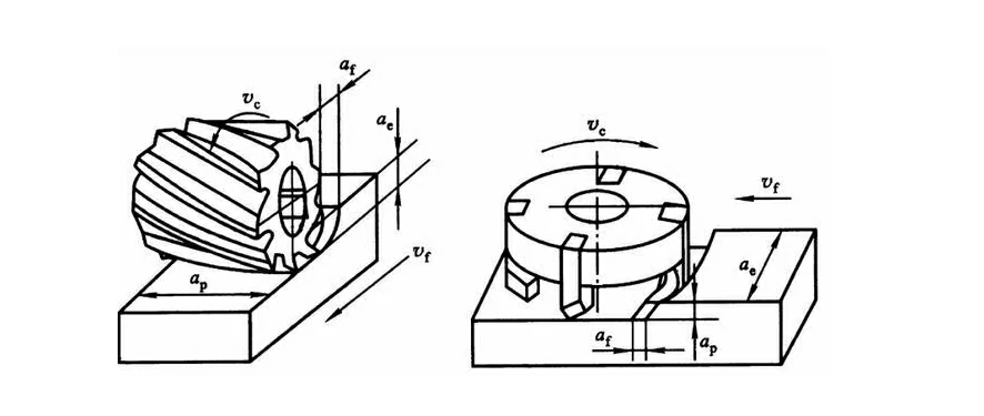
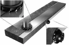
General Face Milling
General face milling (see figure 1) is the most basic and common face milling technique in machining. It can be performed using various types of cutting tools, with tools having a 45° lead angle being the most common.
45° Lead Angle Tools:
- Preferred for general purposes
- Reduce vibration in long overhangs
- Thin chip thickness for increased productivity
90° Lead Angle Tools:
- Thin-walled parts
- Poorly clamped parts
- Situations requiring 90° shaping
Round Insert Cutters:
- Versatile tooling
- Greater cutting edge strength
- Multiple cutting edges per insert
- Suitable for machining heat-resistant alloys
- Provides smooth cutting action
To optimize the general face milling process, machinists can consider the following tips:
- Select the appropriate tool diameter, typically recommended to be 20% to 50% larger than the workpiece diameter.
- When milling parts with poor axial rigidity, use a 90° milling cutter to direct the majority of cutting forces axially.
- Avoid axial depths of cut between 0.5-2mm.
- Utilize sharp positive rake cutting edges to reduce cutting forces, suitable for face milling thin-walled and contoured sections.
- Deviate the entry point from the center of the workpiece to produce thinner exit chips, reducing tool wear and heat buildup.
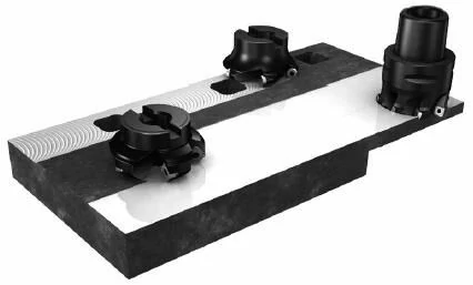
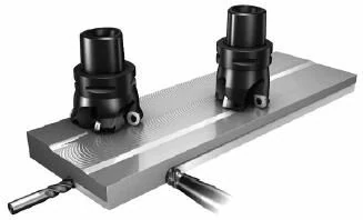
Heavy Duty Face Milling
Heavy-duty face milling (see figure 2) is primarily used for processing large workpieces and removing substantial amounts of material. In this machining method, machinists need to pay attention to cutting forces, cutting temperatures, and tool durability. Face milling cutters with a 60° lead angle are favored for their high feed rates and excellent cutting performance.
The key to optimizing heavy-duty face milling lies in:
When using a magnetic workholding table to clamp the workpiece, a significant amount of chips generated usually tend to accumulate around the tool, leading to chip interruptions or partial chip evacuation, as well as chip recutting, which can jeopardize tool life.
To avoid this situation, it’s essential to maintain a chip-free zone within the machining area. This can be achieved by increasing the axial depth of cut to prevent fragile tool tips from contacting abrasive surface skins and oxides, and shifting the surface contact point to the more robust primary cutting edges of the insert.
High Feed Milling
High-feed milling (see figure 3) is a high-speed cutting method that requires tools to have extremely high cutting speeds and feed rates. When using tools with a small lead angle or round insert cutters, due to the thin chip effect, face milling can be performed at extremely high per-tooth feed rates (up to 4mm/z).
Finishing with Wiper Inserts
Wiper inserts are primarily used for surface finishing. By incorporating wiper inserts along with standard inserts, the surface finish of the workpiece can be further improved. They typically come in different lengths and have left-hand and right-hand versions. The choice depends on the type of standard inserts and the per-revolution feed rate.
Tips To Optimize Face Milling
Face milling techniques are critical skills that machinists must master during the machining process, directly impacting machining efficiency and product quality. Here are some fundamental techniques for face milling:
- Select the recommended spindle speed based on the tooling and workpiece material to avoid excessive tool wear.
- Position the cutting tool slightly off-center from the workpiece center. This positioning can generate thinner chips, reducing resistance during cutting and improving cutting efficiency.
- Avoid frequent entry and exit from the workpiece, which can create unnecessary stress, affecting machining accuracy and tool life.
- When milling in grooves or holes, avoid multiple entries and exits of the workpiece. Alternatively, employ special cutting strategies to address these challenges.
- Introduce CNC technology to achieve automation and precise control of the cutting process.
- Select the appropriate tool type and cutting parameters (such as cutting speed, feed rate, etc.) based on the workpiece material and machining requirements.
- Effectively control the magnitude and direction of cutting forces to avoid excessive cutting forces causing workpiece deformation or tool damage.
Conclusion
Face milling is a key process for smooth surface and precision machining of parts, and selecting the appropriate face milling cutter and optimizing the process are crucial. As a professional milling service provider, BoYi can efficiently handle the milling needs of customized plastic and metal parts, whether it is prototype production or mass production, ensuring both quality and speed. By cooperating with us, you will receive professional and efficient milling services to solve all milling difficulties.
If you have any needs, please contact us and we will provide you with a quotation and feedback within 12 hours.
FAQ
Face milling focuses on milling the top surface of a workpiece, utilizing the cutting tool’s upper section. Conversely, side milling involves milling the workpiece’s sides, expanding the milling action. Face milling is adaptable to both horizontal and vertical spindle machines, whereas side milling is exclusive to horizontal spindle machines.
Facing in milling refers to the process of creating a flat surface at a right angle to the milling cutter’s axis. This involves rotating the facing tool counterclockwise while the workpiece moves across the cutter, effectively removing material.
Face milling positions the cutting tool perpendicular to the spindle, cutting across the workpiece’s surface. Peripheral milling, on the other hand, involves the cutter moving parallel to the surface, maintaining a parallel alignment with the mill.
Face milling boasts several advantages, such as delivering a smooth surface finish, being versatile for various materials like plastics, composites, and metals, and achieving higher feed rates.
Face milling is typically utilized when creating large flat surfaces. It offers a superior surface finish compared to peripheral milling but at a slower material removal rate. While face milling is faster than end milling, it may produce a slightly rougher surface finish.
Tagged: CNC Machining Guide