When producing sheet metal parts, it typically involves multiple processes such as bending, cutting, punching, and welding. These processes add complexity to the creation of sheet metal drawings. Therefore, to achieve optimal results in the design and fabrication of sheet metal parts, it is essential to follow a series of design and fabrication guidelines.
This article will provide a series of key sheet metal design and fabrication guidelines to help engineers and designers understand how to maximize the use of the characteristics of metal sheets, ensuring the feasibility of the design and the efficiency of fabrication.
What is Sheet Metal Drawings?
Sheet metal drawings are a type of mechanical drawing primarily used to depict the details and dimensional specifications of sheet metal fabrication parts. They provide detailed descriptions of the part’s shape, dimensions, material, surface treatments, allowable tolerances, and other pertinent information. Sheet metal drawings serve as the foundation for sheet metal engineers to conduct sheet metal fabrication, aiding them in accurately understanding the structure and requirements of the part, thus enabling precise fabrication.
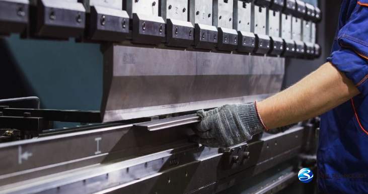
Sheet metal drawing is a manufacturing process used to form flat sheet metal into a desired shape using a die and a press. Used to create complex shapes and structures from flat metal sheets. Sheet metal drawings, on the other hand, detail the parts according to the characteristics and requirements of this processing technique.
The sheet metal drawing process typically involves several steps:
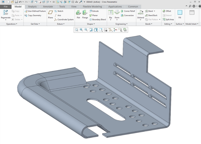
- Design: The design of the final part is created using CAD (Computer-Aided Design) software.
- Material Selection: The appropriate type and thickness of sheet metal are selected based on the requirements of the final part.
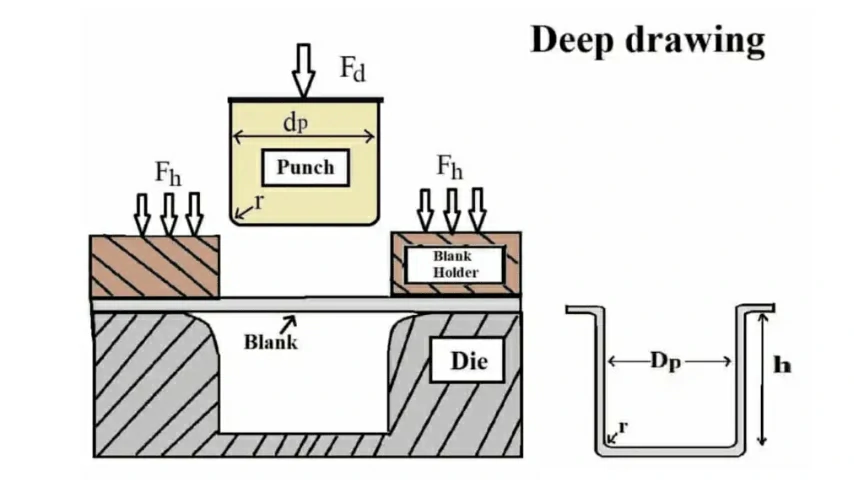
- Tooling Design: The tooling, including the die and punch, is designed to shape the sheet metal into the desired form.
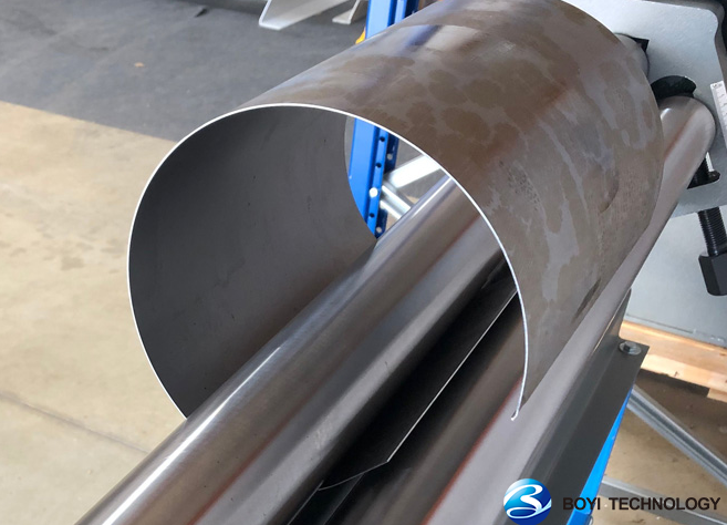
- Blanking: In this step, the sheet metal is cut into a blank of the appropriate size and shape for the drawing process.
- Drawing: The blank is placed over the die, and the punch applies force to draw the sheet metal into the die cavity, forming the desired shape.
- Trimming: After the drawing process is complete, any excess material is trimmed away from the edges of the formed part.
Importance of Creating the Sheet Metal Drawings
Sheet metal drawings are blueprints in the manufacturing process, which not only guide the cutting and shape processing of materials, but also determine the quality and performance of the final product. The following are several key reasons for creating the best sheet metal drawing:
1.Reducing Errors and Rework
Sheet metal drawings provide detailed dimensions, tolerances, and material requirements, helping manufacturers accurately understand design intent and produce products that meet specifications. This significantly reduces manufacturing errors caused by misunderstandings or omissions, thereby reducing rework rates and improving overall project quality.
2.Facilitating Quality Control
Detailed annotations in drawings enable quality control personnel to clearly inspect key points, ensuring that each manufacturing step meets quality standards. This helps to promptly identify and correct potential quality issues, ensuring the reliability of the final product.
3.Minimizing Material Waste
Sheet metal drawings, through rational dimensioning and material selection, help minimize raw material waste. This not only reduces material costs but also facilitates efficient resource utilization.
4.Simplifying Manufacturing Processes
Accurate sheet metal drawings, through optimized design and clear annotations, help simplify manufacturing processes and reduce unnecessary processing steps. This not only shortens production cycles but also lowers production costs.
5.Facilitating External Communication and Coordination
For projects requiring collaboration with suppliers or clients, accurate sheet metal drawings help clarify responsibilities and expectations, reducing communication misunderstandings and disputes. This facilitates the establishment of stable partnerships and promotes the smooth progress of projects.
6.Promoting Cross-Departmental Collaboration
Accurate sheet metal drawings serve as important communication bridges between departments such as design, production, and quality inspection. Through these drawings, each department can clearly understand its responsibilities and requirements, working together to ensure the smooth progress of projects.
Sheet Metal Dimensional Drawing Example
A qualified drawing typically contains a series of crucial information, such as types and thicknesses of materials, surface treatment methods, key dimensions and specifications, revision records, as well as hardware annotations. These details are vital for the machining and assembly of parts, ensuring the smooth progression of the entire manufacturing process.
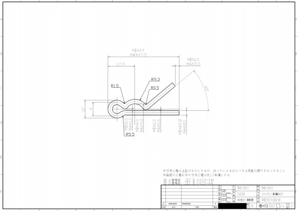
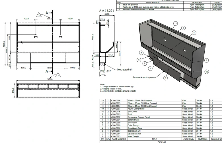
Taking a simple sheet metal part as an example, although its structure is relatively straightforward, the drawing process is relatively easy. However, when it comes to complex assemblies composed of multiple parts, the drawing process becomes more intricate. At this point, a deep understanding of the meanings behind the lines on the drawing, mastery of part manufacturing methods, and familiarity with different types of views are necessary.
What Your Sheet Metal Drawings Should Include?
Your sheet metal drawings should include the following elements:
- Part Geometry:
- Material Specifications
- Dimensions and Tolerances
- Bend Allowance and Bend Deduction
- Feature Annotations
- Surface Finish Requirements
- Assembly Instructions
- Bill of Materials (BOM)
- Revision Information
- Title Block
- Views and Sections
- Notes and Annotations
Purpose of 2D Drawings in Sheet Metal Drawing Process
The purpose of 2D drawings in the sheet metal drawing process is multifaceted and crucial for ensuring the successful fabrication of sheet metal components. Here are some key purposes:
1.Design Communication
2D drawings serve as a visual means to communicate the design intent from engineers or designers to manufacturers and fabricators. They provide a clear representation of the desired geometry, dimensions, tolerances, material specifications, and assembly instructions.
2.Fabrication Guidelines
These drawings contain detailed views of the sheet metal components, including flat patterns, bend lines, hole positions, cutouts, and other critical features. Fabricators rely on these drawings to accurately produce the parts according to the design specifications, ensuring proper fit and functionality.
3.Cost Estimation
Manufacturers use sheet metal drawings to estimate the cost of production by analyzing material requirements, labor, tooling, and other resources needed to manufacture the components. Accurate drawings help in generating more precise cost projections, enabling better budgeting and pricing decisions.
Conclusion
Sheet metal drawings are essential documents in the design and manufacturing process of sheet metal drawing technology. When drawing drawings, relevant standards and specifications should be followed to ensure the accuracy and readability of the drawings.
FAQ
For sheet metal design, many professionals recommend using SolidWorks software. SolidWorks has powerful sheet metal design tools that allow for the rapid, accurate creation, modification, and analysis of various sheet metal parts and assemblies. Other popular software packages include Autodesk Inventor and Fusion 360, CATIA, and Siemens NX.
To read sheet metal drawings, you need to understand the symbols, dimensions, part shapes, manufacturing methods, and maintain careful patience to ensure accurate comprehension.