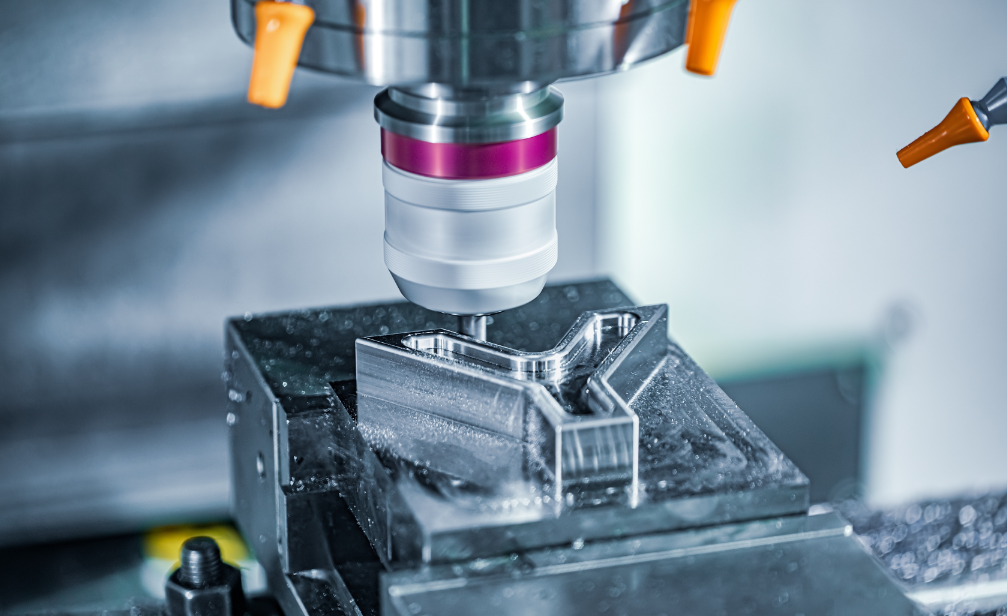
Reaming is one of the precision machining methods for holes, employing a rotational cutting tool. It allows for precisely trimming holes on workpieces, ensuring smooth and accurate inner dimensions. For instance, in plastic products such as plastic pipes and connectors, reaming enhances the accuracy and connectivity of the holes. In metal products like engine blocks, bearings, and turbines, reaming is utilized for meticulous machining to achieve the required dimensional accuracy and surface roughness.
In the machining of components for the automotive and aerospace industries, there are numerous precision assembly holes. They demand strict positional tolerances and high surface roughness requirements. If you’re seeking a professional reaming service provider, BoYi would be your best choice. We possess advanced reaming equipment and a proficient technical team to ensure that every workpiece undergoes meticulous reaming, meeting your expectations for dimensional accuracy and surface quality.
In this guide, BoYi will delve into the definition of reaming, its working principles, applications, various types of reamers, and how to utilize them to achieve unparalleled precision.
What is Reaming?
Reaming is a process focused on refining existing holes (typically performed after drilling or boring) to precision machine the inner surface of the hole. It involves using a cutting tool called a “reamer” to lightly shave the inner walls of the hole, precisely enlarging the existing aperture, and enhancing the surface smoothness of the hole walls. This tool is specifically designed for precision machining, with a low material removal rate that further refines the inner surface quality of the hole, meeting the high precision requirements of parts.
However, in the initial stages of part drilling, most manufacturers tend to use drill bits for rapid cutting. Drill bits, with their efficient material removal capability, can quickly create initial holes in parts. However, it’s worth noting that drill bits are primarily aimed at swiftly removing large amounts of material rather than achieving high precision hole diameters. Therefore, for parts requiring high precision machining, opting for the reaming process is the right choice. In addition, if you want to gain a deeper understanding of the differences between drilling, boring, and reaming, it is recommended that you read the following articles in depth to gain a more comprehensive understanding of the characteristics and advantages of these machining processes, so that you can choose the most suitable process to meet your part manufacturing needs.
Drilling vs. Boring vs. Reaming: Its Process, and Application Difference
How to Ream a Hole: Its Process Principles
Reaming is a critical precision machining method that demands precise operational steps and considerations to ensure optimal machining results. Below is a detailed guide for reaming operations:
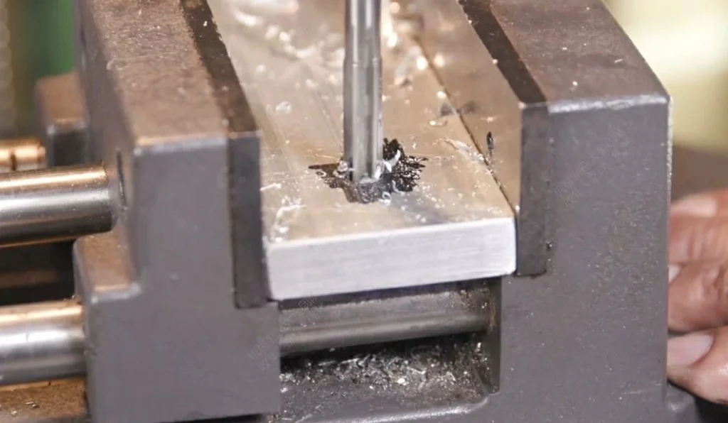
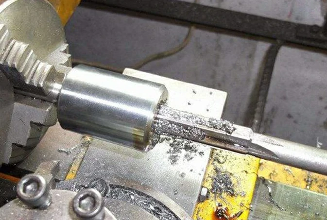
Step 1: Select a typical workpiece according to machining requirements. For example, aluminum alloy, with moderate hardness, is suitable for reaming operations. Choose a reamer with a diameter of 8mm.
Step 2: Use a 7.8mm diameter spotting drill for pre-drilling. The tapered design of the spotting drill helps ensure stability during reaming. The depth of the pre-drilled hole is 20mm, providing a good initial condition for subsequent reaming operations.
Step 3: Insert the reamer into the pre-drilled hole, maintaining the tool’s vertical and horizontal position. Gently rotate the handle to slowly feed the reamer into the workpiece. During the cutting process, observe the chip evacuation, and use an air gun if necessary to prevent chip accumulation from affecting cutting.
Step 4: Set appropriate cutting parameters based on the workpiece material and reamer characteristics. Control cutting speed at 150rpm and feed rate at 0.1mm/rev. Generally, for harder materials, reduce cutting speed and feed rate; for softer materials, increase cutting speed and feed rate appropriately.
Step 5: Once the cutting edge fully enters the workpiece, continue rotating the handle smoothly to guide the tool through the workpiece until the reamer’s cutting edge contacts the workpiece surface. Then, withdraw the reamer by rotating it counterclockwise.
Step 6: After reaming, conduct a comprehensive inspection and measurement of the machined holes. Use a brush to clean the hole bottom and walls, deburring. Utilize high-precision measuring tools to measure the diameter, depth, and surface finish of the holes. The diameter error of the hole should be within ±0.01mm, and the surface finish should meet the requirement of Ra0.8.
During the reaming process, it’s also important to consider the following points:
- During the reaming process, it is also important to note the following:
- Make reasonable use of cutting fluid, selecting the appropriate cutting fluid based on the workpiece material and the condition of the reamer.
- Adjust the coaxiality between the spindle and the tailstock sleeve to within 0.02 to ensure cutting stability.
- Pay attention to changing the position where the reamer stops each time to eliminate the marks caused by the reamer repeatedly stopping in the same place.
- During reaming, the reamer should not be reversed to prevent the reamer from getting stuck between the hole wall and the cutting edge, which may cause scratches on the hole wall or fracture of the cutting edge.
Put your parts into production today
All uploads are secure and confidential.
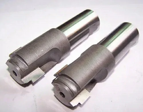
Different Types of Reamer Tools
There are numerous types of reamers, each carefully crafted for specific purposes. In mechanical machining, various types of reamer tools are commonly used, each with unique characteristics and applications. Below, I will detail several common types of reamer tools, along with their specific purposes and usage methods.
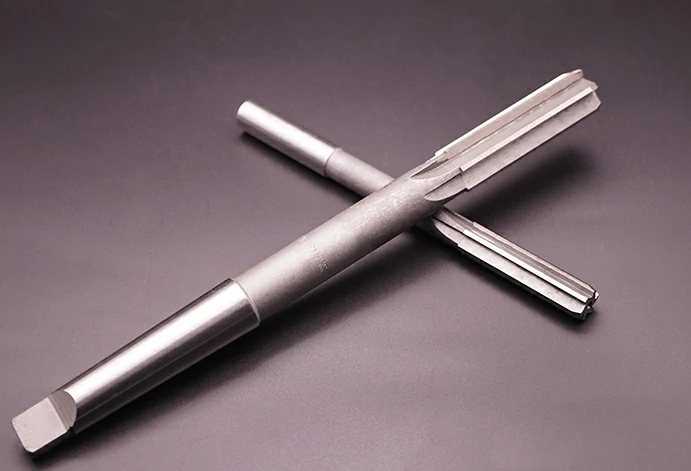
1.Hand Reamers
A hand reamer is a precision-ground cutting tool designed for manual operation, used to manually enlarge pre-drilled holes to precise diameters. These types of reamers typically feature straight or slightly twisted flute designs, with the tip portion having a slight angle and tapered lead-in. This design allows the reamer to easily enter at precise angles during manual operation, especially in situations where there is no machine locking or fixation, although it is not suitable for CNC machines.
Hand reamers are made of hardened, brittle materials, so extra care is needed during use to ensure strict alignment between the reamer and the hole axis to prevent breakage. When manually reaming, operators must ensure that only a small amount of material is removed each time, maintaining precise alignment between the reamer and the hole axis to avoid tool damage or reduced machining accuracy due to improper operation.
Although hand reamers perform well in light cutting operations, their accuracy may not be comparable to machine reamers due to the influence of manual operation factors. Therefore, in applications requiring strict tolerance control, hand reamers may not be the best choice.
2.Shell Reamers
Shell reamers are cutting tools that increase their diameter by rotating a screw, causing the cutting edges to move radially outward. This design not only allows the tool to self-compensate for wear but also enables fine control over different hole diameters. Shell reamers can only remove relatively small amounts of material during the cutting process and may not be as durable as some other more robust tools.
Shell reamers are primarily used for machining larger holes, typically with diameters of 19 mm and above. They can feature any standard flute type, including straight, twisted, and spiral flutes. Different flute types are suitable for different machining needs. When using shell reamers, it is important to maintain tool stability and accuracy to avoid excessive wear or damage.
3.Floating Reamers
A floating reamer is a special type of cutting tool typically mounted on a floating reamer holder, which carries the collet or chuck through an independent bearing system. This design allows for correction of misalignment between the drilled and reamed tool axis, ensuring machining accuracy. It features two replaceable and adjustable cutting edges, fixed in a groove on the reamer, allowing radial float to adapt to different machining requirements.
The advantages of a floating reamer lie in its simple fixture design, easy fabrication, and low cost. It offers high-quality machining, with reamed hole accuracy reaching IT6~IT8 and surface roughness typically ranging from Ra0.8~Ra1.6 or even smaller, meeting high-precision machining requirements. It is particularly suitable for use on boring mills, CNC machining centers, or turn-mill machining centers for applications requiring high-precision reaming.
4.Carbide Reamers
Carbide reamers are cutting tools made of carbide material, known for their high hardness and wear resistance, making them suitable for machining high-hardness, high-strength materials such as stainless steel, titanium alloys, etc. Carbide reamers are mainly divided into straight flute reamers and spiral flute reamers, used to ream holes that have been drilled (or expanded) on workpieces to improve the machining accuracy and reduce surface roughness.
The advantages of carbide reamers lie in their sharp and smooth cutting edges, resulting in smooth hole walls with a surface finish of up to Ra0.25. They offer swift and smooth cutting, excellent chip evacuation, good machine shock resistance, and can maintain hole accuracy tolerances up to 1μ. In batch production, they can be used on machine tools to ream holes in both common and hard-to-machine materials. They are also suitable for CNC reaming for deburring and controlling hole tolerance levels.
However, carbide reamers are extremely brittle, so they must be handled and used with extreme care to avoid fracture and breakage. Additionally, selecting and using cutting fluid is crucial for achieving the best machining results. For example, when machining steel parts, a 10% to 15% concentration emulsion or sulfurized oil is typically used as cutting fluid, while machining castings requires the use of petroleum with good wetting properties and low viscosity. Moreover, cutting fluid must be continuously and adequately supplied to prevent the carbide reamer’s cutting edges from fracturing.
Advantages and Disadvantages of Reaming
The advantages of reaming are mainly reflected in the following aspects:
- High machining efficiency: Reaming typically offers higher efficiency compared to boring. Reaming tools can simultaneously cut two or more surfaces, significantly reducing processing time and improving production efficiency.
- High machining accuracy: During reaming, the tool extends into the hole at a certain angle to the hole wall, allowing for high-precision machining and producing high-quality hole finishes.
- Wide applicability: Reaming is suitable for various connection occasions, such as automotive, bridges, and mechanical equipment, meeting a variety of different machining needs.
- Material saving: Reamed holes for bolt connections do not require special materials. Conventional bolts and nuts can be used for connections, saving material costs.
However, reaming also has some disadvantages:
- Wear when processing small holes: Reamers are prone to wear when processing small holes, requiring frequent replacement or reconditioning, which increases production costs and maintenance difficulty.
- Tool lifespan: The lifespan of reamers may be affected by various factors such as material, cutting fluid selection, and cutting usage. Improper use and maintenance may lead to premature tool damage.
Applications and Considerations of Reaming
To ensure the quality and efficiency of reaming operations, it is essential to have a thorough understanding of its application and considerations.
The amount of allowance in reaming affects the cutting load of the reamer, surface finish, and dimensional tolerance. Therefore, during rough reaming and finish reaming processes, the rough reaming allowance should be controlled between 0.35mm to 0.15mm, while the finish reaming allowance should be controlled between 0.15mm to 0.05mm. This ensures removal of tool marks from previous processes while maintaining the cutting performance of the reamer and the quality of the machined surface.
Furthermore, to avoid chip buildup during reaming, lower cutting speeds are typically used. For example, when high-speed steel reamers are used for machining steel and cast iron, the cutting speed should be below 8m/min, with a feed rate commonly ranging from 0.3mm/r to 1mm/r. As the hole diameter increases, the feed rate value also increases.
In terms of precision requirements, reaming operations can typically achieve high dimensional accuracy and surface roughness requirements. Through proper process planning and operational control, dimensional accuracy of IT9 to IT7 levels and surface roughness of Ra3.2 to 0.8 can be achieved.
During the machining process, attention should be paid to the selection of allowances, control of cutting speed and feed rate, use of cutting fluid, and assurance of machining accuracy. Through proper operation and control, efficient and high-quality hole machining can be achieved.
Put your parts into production today
All uploads are secure and confidential.
Adverse Phenomena Occurring During the Reaming Process
Various problems often arise in the process of reaming. Below, we will introduce how to solve these problems.
1.Diameter of the Hole Increases
Causes:
- The designed outer diameter dimension of the reamer is too large or the reamer edge has burrs.
- The main rake angle of the reamer is too large or the reamer is bent.
- Chip buildup adheres to the reamer edge.
- The deviation of the reamer edge exceeds the tolerance during grinding.
- Surface oil residue or damage on the tapered shank during reamer installation.
- The flat tail deviation of the tapered shank interferes after being inserted into the spindle taper hole.
- Spindle bending or loose/damaged spindle bearings.
- Uneven force applied by both hands during hand reaming causing the reamer to sway.
Solutions:
- Appropriately reduce the outer diameter of the reamer, lower cutting speed, adjust feed rate, or reduce machining allowance as per the specific situation. Reduce the main rake angle appropriately, straighten or discard bent reamers that are unusable.
- Carefully grind the reamer edge with an oilstone to a qualified state and control the deviation during grinding within the allowable range.
- Before installing the reamer, ensure that both the reamer tapered shank and the spindle taper hole are clean of oil residue, and polish any damaged areas on the tapered surface.
- Grind the flat tail of the reamer, adjust or replace spindle bearings to ensure the accuracy of the machine spindle.
- Readjust the floating tap holder and adjust concentricity to ensure stability during the reaming process.
2.Diameter of the Hole Decreases
Causes:
- The designed outer diameter size of the reamer is too small, cutting speed is too low, feed rate is too high, main rake angle of the reamer is too small, inappropriate selection of cutting fluid, partial wear of the reamer during grinding, causing elastic recovery and resulting in hole diameter reduction.
- When reaming steel parts, excessive allowance or dull reamer may result in elastic recovery, causing the hole diameter to shrink, internal hole non-roundness, and non-compliance of the hole diameter.
Solution:
- Replace the reamer with a different outer diameter size, appropriately increase cutting speed, reduce feed rate, increase main rake angle, and choose a lubricating cutting fluid with good performance.
- Regularly interchange reamers and properly grind the cutting part of the reamer. When designing the size of the reamer, consider the above factors or determine values based on actual conditions. Conduct experimental cutting with appropriate allowances to sharpen the reamer.
3.Reamed Inner Hole is Non-Circular
Causes:
- The reamer is too long or lacks rigidity.
- Improper design parameters of the reamer.
- Poor surface quality of the workpiece. Defects such as notches, cross-holes, sand holes, or air holes exist on the inner hole surface.
- Insufficient machine tool accuracy or improper clamping. Loose spindle bearings or absence of guide bushings, or excessive clearance between guide bushings and reamers can lead to instability during reaming.
Solutions:
- For reamers lacking rigidity, consider using a design with unequal pitch to increase stability during cutting. Additionally, rigid connection methods should be used when installing the reamer to ensure that it does not vibrate during cutting.
- Choose qualified reamers to ensure that parameters such as the main rake angle, edge band width, and reaming hole allowance meet the machining requirements. Furthermore, control the positional tolerance of the pre-processing hole to reduce errors during reaming.
- Adjust machine tool accuracy and clamping methods. For loose spindle bearings, adjustments and tightening should be made promptly. During reaming, guide bushings should be used and ensure that the clearance between them and the reamer is appropriate. For thin-walled workpieces, appropriate clamping methods should be used to avoid deformation caused by excessive clamping.
4.Shank of The Reamer Breaks
Causes:
- Excessive reaming allowance, inappropriate allocation of rough and finish reaming allowances during taper reaming, and improper selection of cutting amounts.
- Clogging of the chip space due to small chip clearance between reamer teeth.
Solutions:
- Modify the diameter size of the pre-drilled hole.
- Adjust the allocation of allowances and select appropriate cutting amounts.
- Reduce the number of reamer teeth to increase chip space or grind away one tooth between teeth.
5.High Surface Roughness Value of the Inner Hole
Causes:
- Excessive cutting speed increases cutting force, exacerbating friction between the tool and the workpiece, thereby increasing surface roughness.
- Excessive or insufficient reaming allowance can increase surface roughness. Excessive allowance leads to high cutting force and vibration, while insufficient allowance may leave rough traces on the surface.
- Excessive width of the cutting edge, poor chip removal, excessive wear or damage to the tool can lead to decreased cutting efficiency and increased surface roughness.
- Certain materials may not be suitable for reamers with zero or negative rake angles, resulting in chip lumps during cutting and increased surface roughness.
Solutions:
- Reduce cutting speed to decrease cutting force and friction. Choose appropriate cutting fluid based on the material to improve the cutting environment. Properly reduce the main clearance angle to enhance cutting stability.
- Set the reaming allowance properly to ensure stability during reaming. Improve the accuracy and quality of the pre-drilled hole position to reduce difficulties in subsequent reaming. For insufficient allowance, consider increasing it or using alternative machining methods to improve surface quality.
- Grind the width of the cutting edge to reduce cutting force. Depending on the situation, reduce the number of reamer teeth or increase chip slot space to improve chip removal. Use reamers with rake angles for smoother chip removal. Regularly replace heavily worn reamers to ensure cutting efficiency. Take protective measures during sharpening, use, and transportation to avoid tool damage.
- Choose suitable tool materials and angles for specific materials. Use fine oil stones to remove chip lumps from tools. For materials not suitable for zero or negative rake angle reamers, use reamers with rake angles of 5° to 10° for machining.
When to use Drilling, Boring, and Reaming?
Reaming is commonly used for holes with diameters up to 100mm. When reaming on a machining center, the typical process is drilling (or boring) the hole followed by reaming. For holes with a diameter less than 12mm, the process is adjusted due to the slightly lower rigidity of the reaming tool. The process for smaller holes typically involves spotting, drilling (or boring), and then reaming to ensure the straightness and concentricity of the hole.
Summary
In summary, reaming is a crucial machining process and method of object connection, widely applied across various fields. This article has provided a detailed overview of what reaming is, its working principle, applications, advantages and disadvantages, types of reamers, and when to use reaming. If you need more information or services related to reaming, please contact the Boryi expert team. We prioritize communication and collaboration with our clients, striving to understand your needs and requirements thoroughly to ensure the delivery of the highest quality service experience. Click here to contact us.
Put your parts into production today
All uploads are secure and confidential.
FAQ
The amount of material to leave for reaming, often referred to as the reaming allowance or reaming stock. Typically, leave approximately 1/32″ to 1/16″ (0.8mm to 1.6mm) of material for reaming.
The purpose of reaming the tube before flaring is to remove any burrs, irregularities, or debris from the inner surface of the tube. This ensures a clean, smooth surface for the flare to form properly, resulting in a secure and leak-free connection.
The primary purpose of reaming is to improve the accuracy, surface finish, and diameter of a previously drilled or machined hole. It removes any remaining material, burrs, or imperfections left behind by the initial drilling or machining process. This ensures that the hole meets precise dimensional requirements and is suitable for various applications such as fitting components, creating smooth surfaces for seals, or facilitating assembly processes like threading or inserting fasteners.